Getting Started
In this getting started guide we will see how to blink an led on shrike both on fpga and MCU.
You can program the microcontroller on Shrike using three methods:
1. Arduino (C/C++)
2. MicroPython
3. Circuit-Python
All are beginner-friendly, and you can switch between them anytime.
Let’s follow the steps and get Shrike up and running!
Shrike with ArduinoIDE
If you already know Arduino and love working with the Arduino IDE, you can continue using it with Shrike. You do not have to switch to MicroPython unless you want to.
We will follow these steps to setup our arduino IDE for shrike. If you don’t have arduino IDE already ,you can download it from here or if you are using linux(ubuntu)then just run
sudo apt install arduino
Step 1. Adding the board support for Shrike
The Shrike has a on board RP2040/RP2350/ESP32-S3 has a host controller the Arduino IDE doesn’t native support them however we can add the board support for the same.
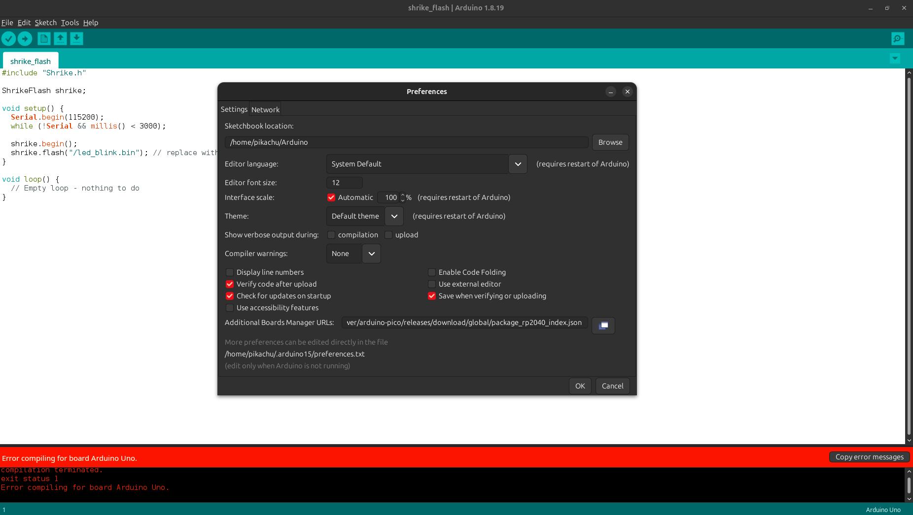
It is quit straight forward we need to add this URL in the addition board URL section of arduino IDE which you can find in File->Preferences.
https://github.com/earlephilhower/arduino-pico/releases/download/global/package_rp2040_index.json
https://raw.githubusercontent.com/espressif/arduino-esp32/gh-pages/package_esp32_index.json
If you already have another board URL just add a “,” between the two URL’s.
These board support had been created by earlephilhower and you can check out github repository for more details.
After adding the URL go to Tools->Boards->Board Manager in the Arduino IDE.
Then search for pico and the board from Earle F. Philhower.
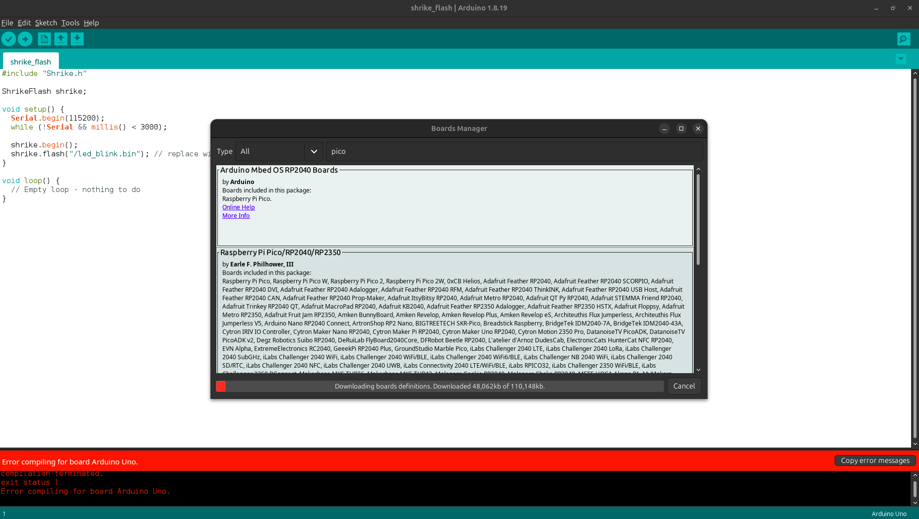
Then search for ESP32 by Espressif Systems.
Perfect we have successfully add the board support for the Shrike.
As we discussed earlier, in Shrike the micro-controller (RP/ESP32) is responsible for configuring the FPGA.
To make this possible, we developed a simple mechanism: we store the FPGA bit-streams in the MCU’s flash memory and retrieve them whenever we need to configure the FPGA. To do this we will need to use a file system called littleFS.
Step 2. Adding the LittleFS Tool
The LittleFS library in Arduino allows you to store, load, and update the bitstream in the flash memory through the microcontroller.
We need to add a Little-FS utility to bind a bin file (FPGA bitstream with code for Shrike). We can find the utility here download the latest release ZIP.
Now for setting up these tools for Arduino IDE version 2.x.x please follow this guide and after proper setup please continue the below steps.
This works for both the RP2040 and ESP32-S3 based boards. ( even tho name says esp32).
You will need to restart the Arduino IDE and you should see the Little FS tool like this in your Tools menu.
For more details on the LittleFS tool checkout this repository.
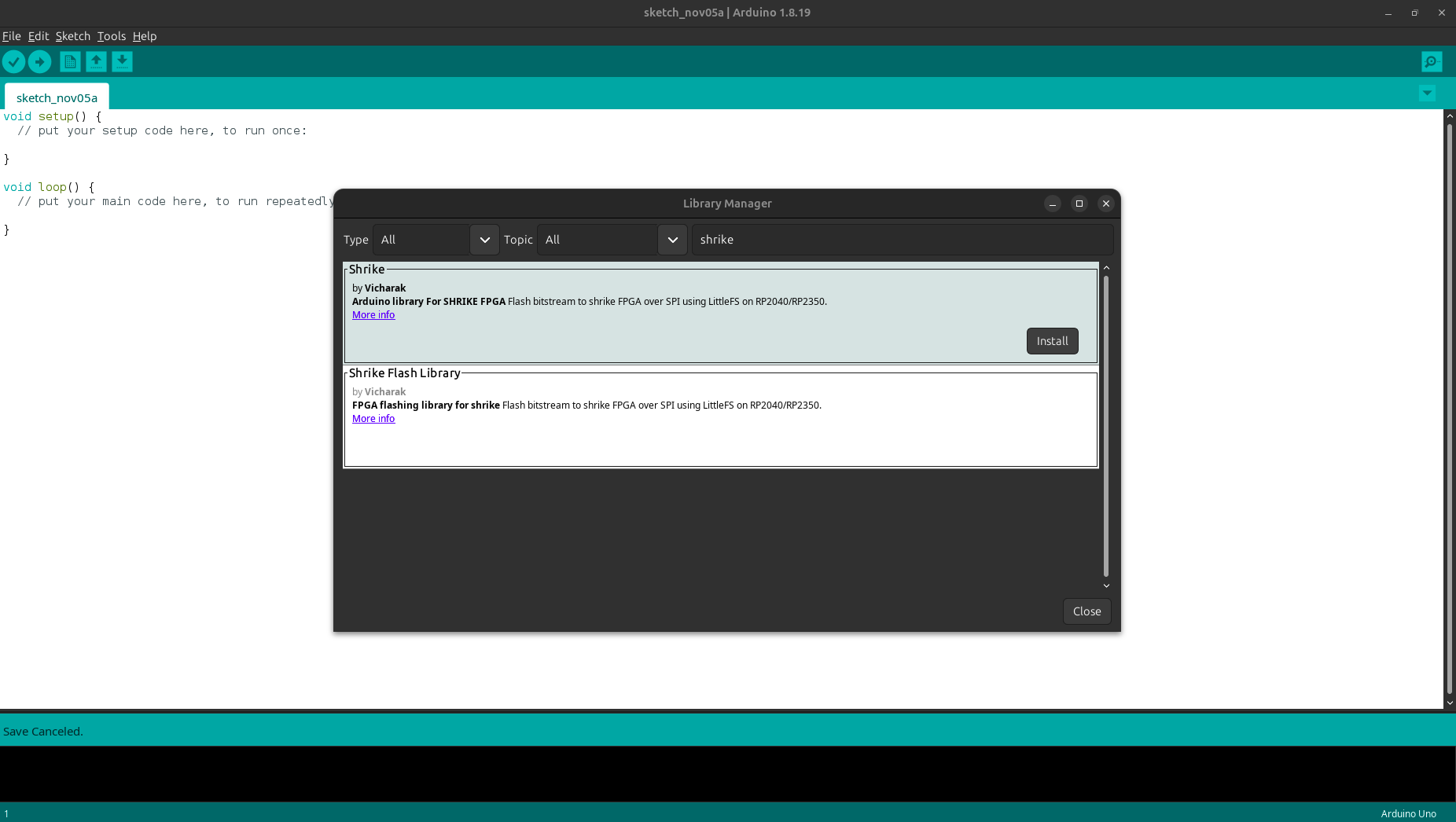
Step 3. Installing the Shrike Library
The Arduino library developed by Vicharak takes care of configuring the FPGA for you. You can install it directly from the Arduino IDE’s Library Manager, just search for “Shrike” and install the Shrike library.
We are almost done with the setup lets continue and blink en led on FPGA using the arduino IDE.
Step 4. Programming the FPGA from ArduinoIDE
Lets program out first bitstream to fpga using the arduino. We will be blinking an led.
Start Arduino IDE and look for Shrike -> shrike_flash in the example section of IDE and then save it with a name of your choice and at a location of your choice. This will create a folder with the name, now in the folder/dir create a subfolder by name data keep the case in mind.
Any bitstream that needs to be uploaded to the board should be placed in the folder. We have already generated and hosted a bitstream to blink led here save this bitstream to the data subfolder.
Checkout guide to learn how to generate your own fpga design here.
Once you have done this, open Arduino IDE and click on Compile. The compilation should complete without any errors. If you encounter any errors, don’t worry,we have a Discord community. Hop in there and we’ll help you out or you can always use claude or chatgpt.
If the compilation has been done without any error then it’s time to connect the board in boot mode “ PRESS THE BOOT BUTTON WHILE CONNECTING THE BOARD WITH PC” ( this should be done only the first time of setting up if arduino are if you have programmed the board with any other way last time).
In the tools section select the Board as VICHARAK Shrike Lite / VICHARAK Shrike based on your board version and flash size as 4MB Sketch:2MB and FS:2MB and CPU Speed as 125 Mhz.
In the tools section select the Board as Generic ESP32-S3 based on your board version and flash size as 8MB Sketch:4MB and FS:4MB .
Now you need to upload the file system to the board to do so press ctrl+shift+p you will see the drop down menu.
Search for Build LittleFS command and run it.
After that in the same menu look for Upload LittleFS command and run that too.
If both of these options are executed properly then then hit upload.
You should see the beautiful blue led blinking on board.
Congratulation you have your arduino IDE and shrike ready to be programmed using the Arduino infrastructure.
Credit and Gratitude to earlephilhower for creating the board support for RP2040/RP2350 in ArduinoIDE and the little FS tool.
Shrike with Micro-python
We have created custom binary for shrike this contains a shrike.py library that has custom function to flash fpga and few other functions as well.
1. Uploading the shrike binary
Download the binary corresponding to your board version from the shrike’s Releases
Hold the boot button on the board and connect it the your pc now shrike will show up as as storage device.
Copy the downloaded uf2 in storage device you can simply drag and drop in mostly all the devices.
After the successful copying the storage device should disappear.
Check the video tutorial on how to upload the uf2 Shrike dev board(its a generic board video and uf2 will differ in our case) here.
Congratulations you have successfully uploaded the uf2.
Shrike Mass Storage Device
Onces that you have copied the uf2 to the Shrike. The board will disconnect momentary and so up as both a mass storage device and tty/ACM device now the mass storage is the part where you would need to save you bitstream (read step 3).
The default device ID for mass storage device is 5221-0000 this could be changed as per your choice.
For windows simply right click and rename for changing the name in linux read this.
Download the binary corresponding to your board version from the shrike’s Releases.
Install the ESP tools
pip install esptool. You might need to activate a python virtual environment. Check this guide to know how to do so.Then execute this command
python -m esptool erase_flashAnd Flash the binary to ESP32-S3 using this command
python -m esptool --chip esp32s3 -b 460800 --before default_reset --after hard_reset write_flash --flash_mode dio --flash_size 4MB --flash_freq 80m 0x0 firmware.bin
Congratulations you have successfully uploaded the binary.
2. Get the bitstream(.bin) for led blink
To program a FPGA you will require bitstream file this is much like a firmware for MCU’s we will see how to generate these but for now we have uploaded the bitstream required for led_bin you can download them the corresponding to your board’s version here.
Now that you have both uf2 and bin file settled up lets move forward and upload the bitstream to board.
3. Getting the Thonny IDE
The bitstream can be uploaded on the shrike using one of these two ways
Using a GUI Based-IDE (Thonny)
Using Command line interface (CLI)
In this guide we will use Thonny however guide to programme using CLI can be found here.
Now we will need to get thonny on our pc. Installation is quite straight forward You can download it from here.
Now that we have got all the required tools set-ed up let blink some leds.
Open thonny and connect the board to the laptop (do not press boot button this time). And do these two things
Connect the board from the bottom right corner of Thonny IDE.
Go to file view mode in the thonny to see the RP2350/RP2040 as a file system.
4. Flashing the bitstream
You should in thonny see both the your pc and Shrike file’s on the left windows now we have to transfer the led_blink.bin file to the Shrike. To do so find the file on your system then right click and upload.
Now we will have to flash this file to the fpga to do so we will use the function
shrike.flash("<your_bitstream_name>.bin")
Note
For any custom project the bitstream file that you need to copy will be named as “FPGA_bitstream_MCU.bin” found in fpga -> build -> bitstream folder in your project directory.
If you copy any other file present in the bitstream folder the fpga wont be programmed.
You are free to change the name of this file however you please.
In thonny open a new python file and write this python script
    import shrike
    shrike.flash("led_blink.bin")
Save this file to your board and run it. (to run this file on board boot up just name it as main.py)
Shrike with Circuit Python
CircuitPython is a programming language designed by adafruit to simplify experimenting and learning to code on low-cost microcontroller boards. It build on a fork of Micropython , thus its seems very similar yet very different.
The way Circuit-Python works with Shrike is we have a custom circuit python build (binary). One must follow these steps to get started with the Circuit-Python on Shrike.
1. Uploading the Shrike binary
Download the binary corresponding to your board version from the shrike’s Release.
Hold the boot button on the board and connect it the your pc now shrike will show up as as storage device.
Copy the downloaded uf2 in storage device you can simply drag and drop in mostly all the devices.
After the successful copying the storage device should disappear.
Check the video tutorial on how to upload the uf2 Shrike dev board(its a generic board video and uf2 will differ in our case) here.
Congratulations you have successfully uploaded the Circuit-Python uf2.
2. Get the bitstream(.bin) for led blink
To program a FPGA you will require bitstream file this is much like a firmware for MCU’s we will see how to generate these but for now we have uploaded the bitstream required for led_bin you can download them the corresponding to your board’s version here.
Now that you have both uf2 and bin file settled up lets move forward and upload the bitstream to board.
The board will showing up as a storage device on the pc now copy the downloaded bitstream to the board.
3. Getting the Thonny IDE
Now we will need to get thonny on our pc. Installation is quite straight forward You can download it from here.
Now that we have got all the required tools set-ed up let blink some leds.
Open thonny and connect the board to the laptop (do not press boot button this time). And connect the board from the bottom right corner of Thonny IDE.
4. Flashing the bitstream
The custom binary of circuit-python contain a python library for flashing and resting the fpga and a few other functions as well.
So we will use this library to flash this bitstream file to the fpga, to do so we will use the function
shrike.flash("<your_bitstream_name>.bin")
If you are using the test bitstream provided by use it is named as led_blink.bin
Note
For any custom project the bitstream file that you need to copy will be named as “FPGA_bitstream_MCU.bin” found in fpga -> build -> bitstream folder in your project directory.
If you copy any other file present in the bitstream folder the fpga wont be programmed.
You are free to change the name of this file however you please.
In thonny open a new python file and write this python script
    import shrike
    shrike.flash("led_blink.bin")
Save this file to your board and run it. (to run this file on board boot up just name it as main.py)